
More Guides
No single loudspeaker driver can reproduce the whole audio band well. A cone big enough to move air at 30 Hz is far too heavy to respond at 15 kHz; a dome light enough for the treble would destroy itself attempting bass. So speakers use two or three drivers and divide the signal between them — and the circuit that performs that division, the crossover, has to do it so cleanly that the transition is inaudible. It is the part of a speaker that most often separates a good design from an ordinary one, and it is invisible from the outside.
What the Crossover Actually Does
At its simplest, a crossover is a set of filters. A low-pass filter sends only low frequencies to the woofer; a high-pass filter sends only high frequencies to the tweeter; in a three-way design a band-pass section feeds the midrange. The frequency where responsibility passes from one driver to the next is the crossover frequency, and near it both drivers are producing sound together.
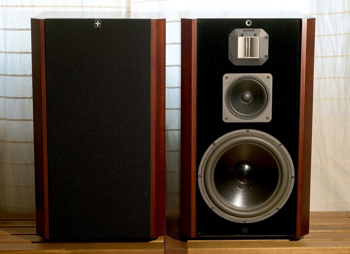
That overlap region is where all the difficulty lives. The two drivers are physically separated on the baffle, so their outputs arrive at your ears at slightly different times and from slightly different directions. Each driver's response is already rolling off naturally at the extremes of its range, so the electrical filter combines with the driver's own acoustic behaviour rather than acting on a flat starting point. Getting a summed response that is flat, and that stays flat as you move around the room, is genuinely hard.
Filter Order and Slope
Filters are described by their order, which sets how steeply they attenuate outside the passband. Each order adds 6 dB per octave of slope and 90 degrees of phase shift at the crossover point.
- First order (6 dB/octave) — the gentlest. Excellent phase behaviour and, in theory, perfect summing, but a very wide overlap region means both drivers work far outside their comfortable range.
- Second order (12 dB/octave) — a common compromise. Narrower overlap; the standard Linkwitz-Riley variant requires inverting one driver's polarity to sum flat.
- Third order (18 dB/octave) — tighter still, with good driver protection and a characteristic phase relationship between sections.
- Fourth order (24 dB/octave) — the workhorse of modern design, particularly as a Linkwitz-Riley alignment, which sums flat with both drivers in phase at the crossover point.
Steeper is not automatically better. A steep filter minimises the overlap region and protects the tweeter from damaging low-frequency energy, but it uses more components — each with losses and tolerances — and introduces more phase rotation. A gentle filter preserves phase relationships but demands drivers that behave well over a much wider range. Designers choose the order to suit the drivers, not the other way round.
Where the Handover Should Happen
The crossover frequency is constrained from both sides. It must be high enough that the tweeter is not asked to reproduce energy near its resonance, where excursion and distortion rise sharply — typically at least two octaves above the tweeter's own resonant frequency. It must be low enough that the woofer is not still working where it has become directional, since a large cone beams at higher frequencies and the sudden change in dispersion at the handover is audible as a tonal shift off-axis. For a typical 25 mm dome with a 165 mm woofer, that puts the answer somewhere around 2–3 kHz — awkwardly, right in the region where hearing is most sensitive.
Passive Crossovers: After the Amplifier
A passive crossover sits between the amplifier and the drivers, filtering a full-power signal with inductors, capacitors and resistors. It requires no additional amplification, no power supply and no setup, which is why the overwhelming majority of speakers use one.
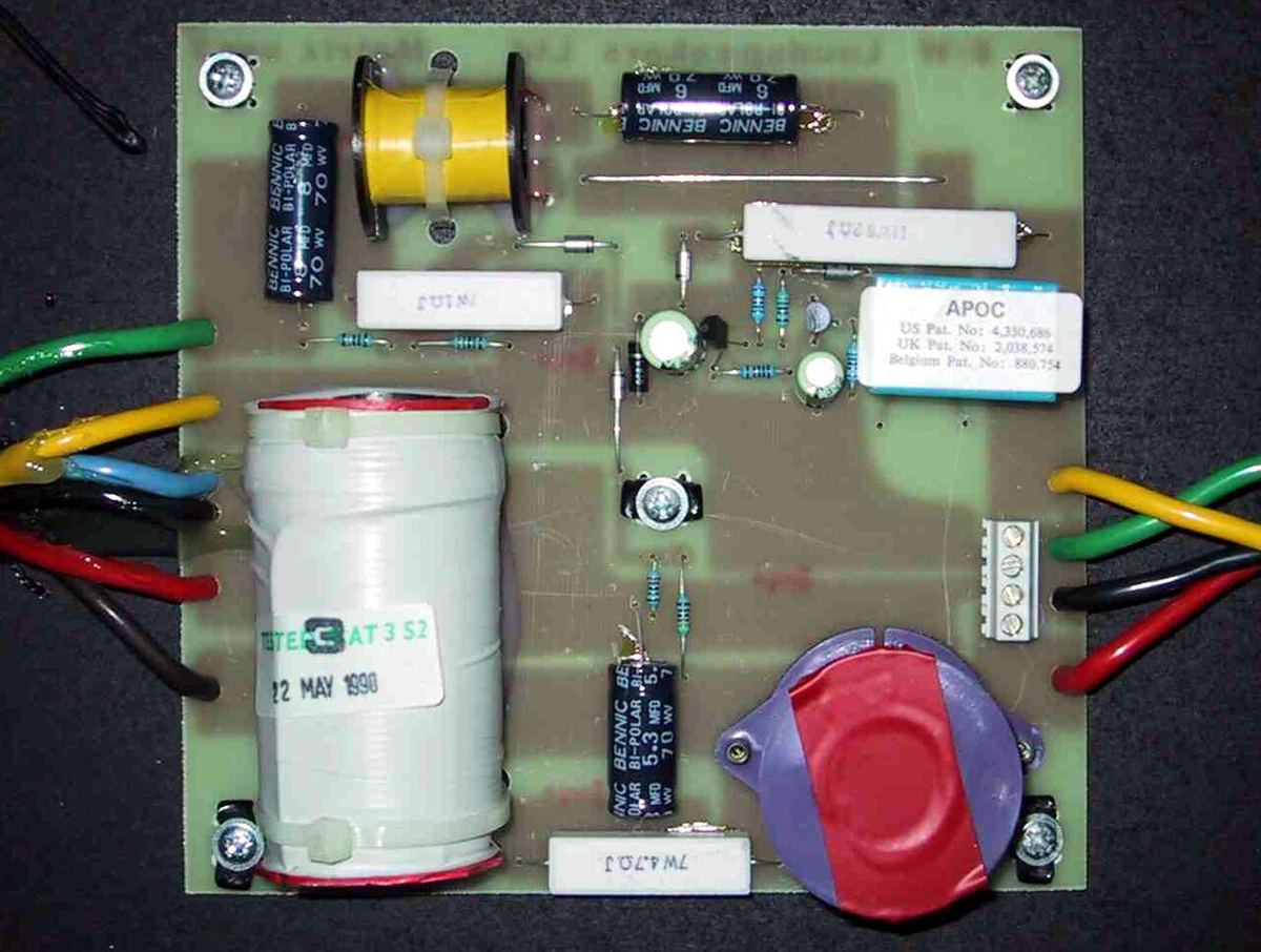
The costs are real, though. The components handle full amplifier power, so they must be large and rated accordingly — and they dissipate some of that power as heat, which is a direct efficiency loss. Inductors have resistance that adds to the driver's impedance and reduces the amplifier's control over the cone. Component tolerances directly shift the filter's behaviour, so a good passive crossover uses tightly matched parts, which is expensive. And because the filter interacts with the driver's own impedance, which varies with frequency, designers often add impedance-correcting networks that add still more components in the signal path.
The passive crossover is also the main reason speakers present difficult loads to amplifiers. Sharp impedance dips and severe phase angles usually originate here rather than in the drivers themselves.
Active Crossovers: Before the Amplifier
An active crossover filters at line level, ahead of the amplification, and each driver then gets its own amplifier channel connected directly. The advantages follow immediately: filtering a small signal costs almost no energy, filter accuracy is far higher, each amplifier sees a simple driver load rather than a network, and there is nothing between amplifier and voice coil to blunt control.
Active designs also unlock things passive cannot do at all — independent level trimming per driver, time alignment by delaying the closer driver, and arbitrary filter shapes when implemented in DSP. This is why studio monitors and most modern powered speakers are active, and why active bi-amping is the version of bi-amping that produces a substantial improvement.
The cost is boxes, channels and complexity: a three-way active speaker needs six amplifier channels for a stereo pair, plus the crossover itself, plus correct setup. In an integrated active speaker the manufacturer handles all of that, which is much of the appeal.
Phase, Lobing and the Vertical Axis
Two drivers producing the same frequency from different points on a baffle interfere with each other, and the pattern of that interference changes with listening angle. Around the crossover frequency, the combined output forms a lobe that may not point straight forward, and above and below that lobe there can be cancellation.
This is why a speaker can sound tonally different standing up than sitting down, and why tweeter height matters so much. Designers manage it by choosing filter alignments that keep the drivers in a favourable phase relationship, by adjusting the physical offset of the drivers on the baffle, by sloping the baffle, and sometimes by inverting a driver's polarity so the summed lobe aims at the listener. It is also the main argument for keeping the crossover region tidy: whatever happens at the handover happens differently at every angle.
Baffle step is part of the crossover's job too. At low frequencies a speaker radiates into the full sphere behind it as well as in front; as frequency rises past the point where the baffle becomes large compared to the wavelength, radiation is confined forward and on-axis output effectively rises by up to 6 dB. Left uncorrected this makes a speaker sound thin. Baffle step compensation in the crossover deliberately reduces the upper range to match, which costs sensitivity — one reason small speakers on stands are less efficient than their driver specifications suggest.
What This Means When You Are Buying
You cannot audition a crossover, but you can look for the consequences of a good one.
Listen off-axis, both horizontally and vertically. A speaker whose tonal balance holds up as you move your head has a well-managed crossover region; one that changes character sharply when you stand does not. Check the published impedance minimum and phase angle if available, since a benign load usually indicates a crossover designed with care rather than one fighting the drivers. And be sceptical of the marketing arithmetic that counts components — more parts in a passive crossover is not a virtue, and the goal is the flattest, most consistent summed response with the fewest elements in the path.
A Worked Example: What the Components Look Like
The simplest crossover makes the principles concrete. A first-order filter uses a single component per driver: a capacitor in series with the tweeter to block bass, and an inductor in series with the woofer to block treble. For a crossover frequency f into a resistance R, the values are C = 1 ÷ (2πfR) and L = R ÷ (2πf).
At 2.5 kHz into 8 Ω, that gives a capacitor of about 8 µF and an inductor of about 0.51 mH. The catch is that a driver is not an 8 Ω resistor. A woofer's impedance rises steadily with frequency because of its voice-coil inductance, so the filter that looked correct on paper crosses over somewhere else in practice. That is why real crossovers so often include a Zobel network — a resistor and capacitor across the woofer that flatten its rising impedance — and why the values in a finished design are tuned against measurements of the actual drivers in the actual cabinet rather than taken from a formula.
The Hidden Cost of Inductors
The woofer's inductor sits directly in series with the voice coil, and its resistance matters. An air-core inductor of a few millihenries, wound from moderately thick wire, commonly measures somewhere around 0.3–0.8 Ω. Against a woofer voice coil of 6 Ω, an extra 0.5 Ω costs about 0.7 dB of bass output and raises the driver's electrical Q.
Put that alongside the amplifier side of the equation. A solid-state amplifier's output impedance is typically a few hundredths of an ohm, so the crossover inductor can be ten or twenty times larger than the source impedance the damping-factor specification describes. Designers can reduce it with thicker wire or a ferrite or laminated iron core, which lowers resistance at the cost of possible saturation at high current. It is one of the more honest reasons a well-built passive crossover costs more: much of the expense is in low-loss inductors.
Matching Driver Levels
Drivers rarely share the same sensitivity. Tweeters in particular are often several decibels more sensitive than the woofers they are paired with, so the crossover must also pad the tweeter down. The usual tool is an L-pad: one resistor in series with the tweeter and one in parallel with it, chosen so the amplifier still sees the right impedance while the tweeter receives less voltage.
For a 6 Ω tweeter that needs 4 dB of attenuation, the values come to roughly 2.2 Ω in series and 10.3 Ω in parallel; the combined network still measures about 6 Ω. Those resistors dissipate power that never becomes sound, which is part of why passive speakers are less efficient than their drivers' raw sensitivity figures suggest. Some speakers expose a tweeter-level switch or link on the back panel; it is usually selecting between L-pad values, and it is a legitimate way to adjust treble balance for a bright or dull room.
Two-Way or Three-Way?
A three-way design adds a dedicated midrange driver, which lets each driver work over a narrower band and moves the woofer-to-midrange crossover down, often to somewhere in the 300–600 Hz range, well below the region where hearing is most sensitive. The midrange can be small enough to disperse widely through the voice band, and the woofer no longer has to reproduce vocals while handling deep bass excursion.
The cost is a second crossover region, more components, more drivers to integrate and a more complex vertical lobing pattern. A well-executed two-way frequently sounds more coherent than a mediocre three-way, so driver count is not a ranking. It is a design choice that tends to pay off in larger, louder, full-range speakers and matter less in compact standmounts.
Quick Reference: Crossover Characteristics
| Aspect | Passive | Active |
|---|---|---|
| Where it filters | After the amplifier, at full power | At line level, before amplification |
| Power loss | Real — dissipated as heat in components | Negligible |
| Amplifier channels needed | One per speaker | One per driver |
| Filter precision | Limited by component tolerance and driver impedance | High; DSP allows arbitrary shapes |
| Driver control | Reduced by inductor resistance in the path | Direct amplifier-to-driver connection |
| Level and delay trimming | Fixed at design time | Adjustable per driver |
| Typical filter order | Second to fourth | Any, commonly fourth-order Linkwitz-Riley |
See how your speakers load your amplifier
Enter your speakers and amplifier for a free analysis of impedance behaviour, power delivery, and whether the pairing has the current it needs.
Run a Free Analysis →