
More Guides
Damping factor appears near the top of most amplifier specifications, often as an impressively large number: 200, 800, sometimes over 1,000. It describes something real — how firmly an amplifier can control the motion of a loudspeaker cone — but the published figure is measured under conditions that do not survive contact with a real system. Once cable and voice coil are included, a specification of 1,000 and one of 200 can produce almost identical results. This guide explains the ratio, the physics behind it, and where the number stops being useful.
The Definition, and Why It Is a Ratio
Damping factor is simply the speaker's nominal impedance divided by the amplifier's output impedance:
Damping factor = load impedance ÷ amplifier output impedance
An amplifier with an output impedance of 0.05 Ω driving an 8 Ω speaker has a damping factor of 160. The same amplifier into a 4 Ω speaker has a damping factor of 80 — the amplifier has not changed, only the load. This is the first thing to notice: damping factor is not a property of the amplifier alone, and a figure quoted without stating the load is meaningless.
Because the load is fixed by your speakers, the only variable the amplifier controls is its own output impedance. A high damping factor is another way of saying the amplifier has a very low output impedance — it behaves close to an ideal voltage source, holding its output voltage steady regardless of what the load does.
What It Physically Does
The reason any of this matters is that a loudspeaker driver is also a generator. Once the cone is moving, its voice coil is a coil of wire moving in a magnetic field, and it produces a voltage of its own — back-EMF. That is most pronounced around the driver's resonant frequency, in the bass, where the cone has the most mass and the most inclination to keep moving after the signal has stopped.
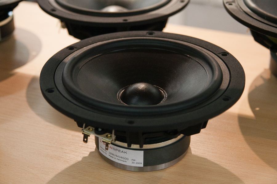
An amplifier with low output impedance presents an almost short circuit to that back-EMF. The current it generates flows, is opposed by the driver's own motor, and the cone's excess motion is converted to heat and damped away. An amplifier with high output impedance cannot absorb it as effectively, and the cone rings on for longer. In audible terms this is the difference between a bass note that stops when the music stops and one that overhangs into the next.
The Voice Coil Sets a Hard Ceiling
Here is the fact that reframes the whole specification. The electrical damping of a driver depends on the total resistance in the circuit — and the largest part of that is the driver's own voice coil, typically 5–7 Ω of DC resistance in a nominally 8 Ω driver. The amplifier's 0.05 Ω and the cable's 0.1 Ω are small additions to a number that is already around 6 Ω and cannot be reduced. This is why the effective damping seen by the cone changes so little between an amplifier with a damping factor of 200 and one with 1,000.
Cable Resistance Joins the Amplifier's Side
Everything between the amplifier's output devices and the speaker terminals adds to the source impedance, and speaker cable is the biggest contributor. The relevant figure is the resistance of the full loop — out and back — over the length you actually use.
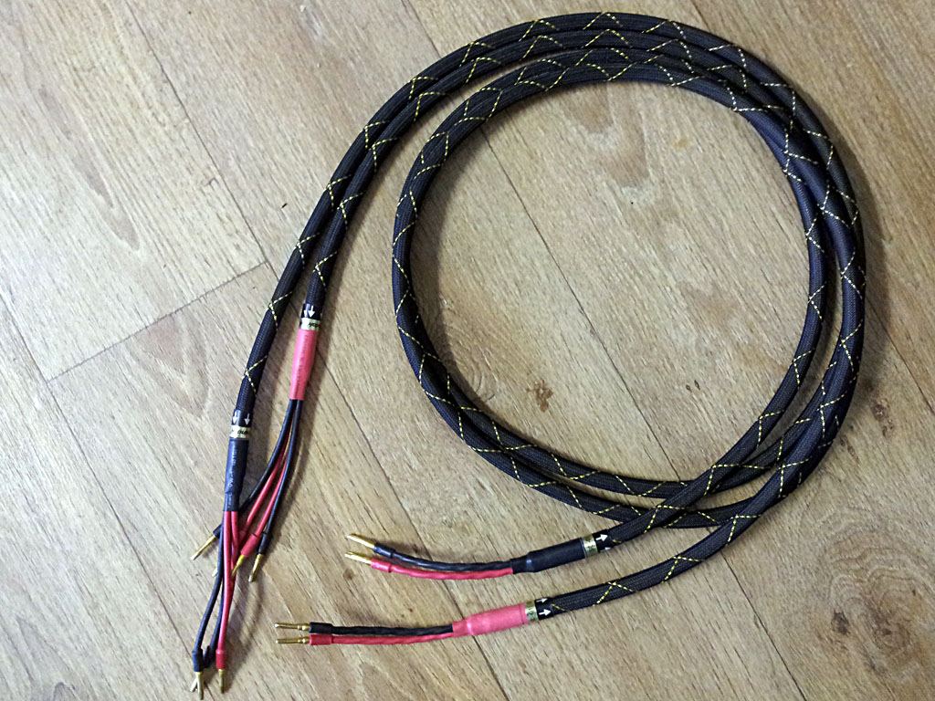
The numbers are easy to underestimate. A 3 m run of 16 AWG cable contributes roughly 0.08 Ω for the round trip. Against an amplifier output impedance of 0.02 Ω, the cable has just multiplied the total source impedance by five and cut the effective damping factor by about four-fifths. Move to 5 m of thinner cable and the effect grows further. The published figure of 400 quietly becomes something under 80 by the time the signal reaches the driver.
This is the practical takeaway that damping factor actually supports: choosing adequate cable gauge for the run length is worth real attention, while chasing amplifiers with ever-higher damping specifications is not. Thicker cable over long runs genuinely improves the number that reaches the speaker.
The threshold that matters: once the total source impedance is well below the driver's voice coil resistance, further reductions change the cone's behaviour very little. In practice, a damping factor of around 50 into the actual load is comfortably adequate, and above roughly 100 the differences are academic. Numbers in the hundreds or thousands are marketing headroom, not audible benefit.
Why Some Excellent Amplifiers Have Low Figures
Valve amplifiers routinely publish damping factors between 2 and 20, far below any solid-state design, because an output transformer places real impedance between the output devices and the speaker. Single-ended triode designs can be lower still. By the logic of the specification alone these amplifiers should be uncontrolled and boomy — and yet many are well regarded.
Two things explain it. First, a high output impedance means the amplifier's frequency response follows the speaker's impedance curve: where impedance rises, output voltage rises. With a speaker whose impedance peaks in the bass, this produces a warmer, fuller balance that many listeners like. Second, valve amplifiers are usually paired with speakers chosen to suit them — sensitive designs with benign, relatively flat impedance curves, which minimise the interaction. The specification is not wrong; it simply describes a different design philosophy in which the amplifier and speaker are treated as a matched pair rather than as independent boxes.
The same principle explains why speaker choice matters more with a low-damping amplifier. A speaker with a wildly varying impedance curve will have its frequency response audibly reshaped; one with a smooth curve will not.
How to Use the Specification Sensibly
Damping factor is best treated as a coarse screening tool rather than a ranking. A handful of checks extract everything it has to offer.
- Check the load it is quoted into. A figure without "into 8 Ω" attached is incomplete; halve it mentally for a 4 Ω speaker.
- Check the frequency. Output impedance usually rises at high frequencies, so a figure quoted at 1 kHz will be better than the reality at 10 kHz. It is the bass figure that matters for cone control anyway.
- Treat 50 as adequate and 100 as plenty into your actual load, for solid-state designs.
- Spend the attention on cable gauge instead. For runs over about 3 m, moving from 16 AWG to 14 or 12 AWG does more for effective damping than any amplifier upgrade chasing the specification.
- For valve amplifiers, ignore it and match the speaker. Look for sensitivity and a smooth impedance curve rather than a damping number.
A Worked Example: Following the Numbers to the Cone
Take a solid-state amplifier specified at a damping factor of 400 into 8 Ω, which means an output impedance of 0.02 Ω. Connect it with 4 m of 16 AWG cable — 8 m of conductor for the round trip, at roughly 0.013 Ω per metre, so about 0.106 Ω. The source impedance seen at the speaker terminals is now 0.126 Ω, and the effective damping factor is 8 ÷ 0.126, or about 63. The specification sheet said 400; the speaker sees 63.
Now go one step further, to the driver itself. The quantity that actually governs how well the cone is controlled electrically is the driver's electrical Q, which rises in proportion to the total resistance in the circuit: voice coil plus everything feeding it. Suppose a woofer with a 6 Ω voice coil and an electrical Q of 0.40 when driven from a perfect zero-impedance source. Add 0.126 Ω and the Q becomes 0.40 × 6.126 ÷ 6, or about 0.408 — a 2% change. Swap the amplifier for one with a damping factor of 1,000 and the result is 0.408 again, to three decimal places. The spectacular specification difference has all but vanished by the time it reaches the cone.
Repeat the exercise with a valve amplifier of 1 Ω output impedance, a damping factor of 8. Total source impedance is now about 1.1 Ω, and the Q rises to roughly 0.47, an 18% increase. That is enough to change the bass: slightly fuller, slightly less tightly controlled around the driver's resonance. So the specification does separate amplifier types — but the meaningful line falls somewhere around single digits to the low tens, not between 200 and 1,000.
The Effect You Can Actually Hear: Frequency Response
Cone control is the effect damping factor is named for, but the more audible consequence of output impedance is usually a change in frequency response. The amplifier's output impedance and the speaker's impedance form a voltage divider, and a speaker's impedance is anything but constant: a nominal 8 Ω design might dip to 3.5 Ω in the upper bass and peak at 30 Ω at its bass resonance or around the crossover.
With the 0.126 Ω source from the example above, the level at the speaker falls by 0.31 dB at the 3.5 Ω dip and 0.04 dB at the 30 Ω peak — a variation of about a quarter of a decibel, which is inaudible. With the 1.1 Ω valve source, the same speaker loses 2.4 dB at the dip and 0.3 dB at the peak: a 2 dB response variation that follows the impedance curve exactly. That is clearly audible, and it is why the same valve amplifier can sound balanced on one speaker and lumpy on another.
This is also the most practical way to judge whether a low damping factor will matter in your system. Look at the speaker's impedance curve rather than its nominal rating. If it is flat, a high output impedance changes little; if it swings widely, the amplifier will reshape the response wherever the curve moves.
Bridging and Class D
Two further details affect the number in practice. Bridged operation, where two amplifier channels drive one speaker in opposite polarity, places the two output impedances in series, so the damping factor into a given load halves. A bridged amplifier specified at 200 per channel offers about 100 when bridged.
Class D amplifiers need an output filter to remove their switching frequency, and in some designs that filter makes output impedance rise noticeably in the top octave, so the damping figure quoted at low frequencies flatters the treble. Modern designs that apply feedback after the filter largely avoid this, and in the bass — where damping matters — good Class D amplifiers typically measure as well as any linear design.
Quick Reference: Damping Factor in Context
| Item | Typical Value | Effect on Control |
|---|---|---|
| Amplifier output impedance (solid-state) | 0.01–0.1 Ω | Small part of the total; the published spec's only variable |
| Speaker cable, 3 m of 16 AWG (round trip) | ~0.08 Ω | Often exceeds the amplifier's own contribution |
| Speaker cable, 3 m of 12 AWG (round trip) | ~0.03 Ω | Meaningful improvement on longer runs |
| Driver voice coil DC resistance | 5–7 Ω | Dominates the circuit; cannot be reduced |
| Damping factor of 50 into the real load | — | Adequate for firm bass control |
| Damping factor above ~100 | — | Differences are academic; not an upgrade path |
See how your amplifier controls your speakers
Enter your amplifier, cable and speakers for a free analysis of load matching, effective damping, and whether your cable run is costing you control.
Run a Free Analysis →